
Click here for Air Handling Unit (AHU) Component Selection Guide.
BTU of the coil side(High side) should match the BTU of the air side(Low side).
Water side / High side:
Typical values are
- Chilled water-in 44° F
- Chilled water-out 54° F
- Estimated Δt - 10° F
- Chilled water pressure drops - max. 20 ft of H2O
- Flow rate - 2.4 gpm/ton
- Water velocity – 2 fps ~ 3 fps
A typical chilled water system gives water at 44° F to an AHU at the inlet.
Measure the water flow rate at the inlet of the AHU. We can measure the flow rate using an analog/digital manometer OR an ultrasonic flowmeter installed on the chilled water pipe.
Click here for Chilled water flows measurement using Orifice plate, Balancing valves, Manometers & Pitot tubes.
Typical AHU requires a flow rate of 2.4 gallons/ton. So, the flow rate should be 24 gpm for the AHU capacity of 10 TR.
A typical AHU will have a Δt of 10° F, hence we assumed the AHU coil outlet temperature as 54° F.
Refer water system cooling load calculations for formulae and derivations.
For the above assumed parameters we can calculate the cooling load as
Btu/hr 	= 500 x gpm x Δt
	= 500 X 24 gpm x (44° F - 54° F)
	= 120000
	= 120000 / 12000 tons = 10 tons
Air side / Low side:
For simplicity consider there is no fresh air addition, AHU fan motor heat gain, and infiltration.
Also a typical cooling and dehumidification process is considered in this example.
Use “sling psychrometer” and take the below readings at the AHU inlet.
- DBT = 75° F
- WBT = 68° F
AHU inlet is same as the “return air from room” / “room air temperature” / “required zone air conditions”.
Also, take the below readings at the AHU coil outlet.
- DBT = 57° F
- WBT = 56° F
Coil leaving air temperature will be slightly higher than the coil surface temperature & chilled water outlet temperature. Here the assumed chilled water outlet temperature is 54° F. Leaving air temperature is dependent on
- The surface area of the coil in contact with the air stream
- The velocity of the air stream
Higher the contact area and higher the time in contact with the surface gives less temperature difference and better efficiency. At 100% efficiency, the coil leaving air dry bulb temperature (DBT) will be equal to wet bulb temperature (WBT) since the air is saturated. We usually get a temperature difference of less than 1° F between DBT and WBT hence 100% efficiency is always not possible.
Resolve other psychrometric properties of air at inlet & outlet of the AHU coil.
Refer Psychrometric chart, properties calculator and related equations.
The below specified values in the table were taken from the psychrometric properties calculator & not the from the chart.
| Property | Description | Values @ Inlet | Values @ Outlet |
|---|---|---|---|
| HR (OR) AH | Humidity Ratio (OR) Absolute Humidity | 0.013 lb/lb | 0.0093 lb/lb |
| VP | Vapour Pressure | 0.302psia | 0.217 psia |
| RH | Relative Humidity | 70.3% | 94.16% |
| DP | Dew Point Temperature | 64.7° F | 55.4° F |
| H | Enthalpy | 32.3 Btu/lb | 23.8 Btu/lb |
| SV | Specific Volume | 13.76 ft3/lb | 13.22 ft3/lb |
Calculate the air flow rate in CFM (cubic feet per minute) passing through the AHU coil, using an Anemometer.
Assumed measured flow rate is given below.
Air flow rate in CFM = 3000
Total cooling load can be calculated using the above enthalpy values & air flow rate
Total cooling load Q<sub>total</sub> = 4.5 * CFM * ΔH
= 4.5 * 3000 * (32.3 - 23.8)
= 114,750 Btu/hr
= 9.56 Tons
Refer air side energy calculation for the equations and calculate the below values
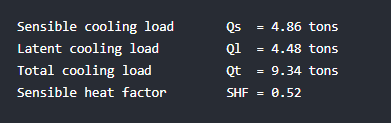
Sensible cooling load 		Qs 	= 4.86 tons
Latent cooling load		Ql 	= 4.48 tons
Total cooling load		Qt 	= 9.34 tons
Sensible heat factor		SHF 	= 0.52
Refer ADP and BF calculation for the equations and calculate the below values
Apparatus dew point temperature ADP 	= 53.7° F
By-pass factor				= 0.15