
Introduction:
Selection of AHU includes the type of AHU, filters, coils, panels, fans, and a few other components. Any change in specification of these items directly affects the performance, quality, capacity, and cost of the air handling units. This document explains various terminology and standards used in the industries at the macro level. The readers are advised to refer to the latest standards & manufacturer data to get specified accurate information.
Click here for Air Handling Unit (AHU) performance calculation.
Types of AHU
- Horizontal floor mount - All major components are aligned to the base tray and it makes maintenance-friendly.
- Vertical floor mount – Designed to occupy less space
- Ceiling suspended – Hanged from the ceiling inside the “false ceiling” and zero floor space.
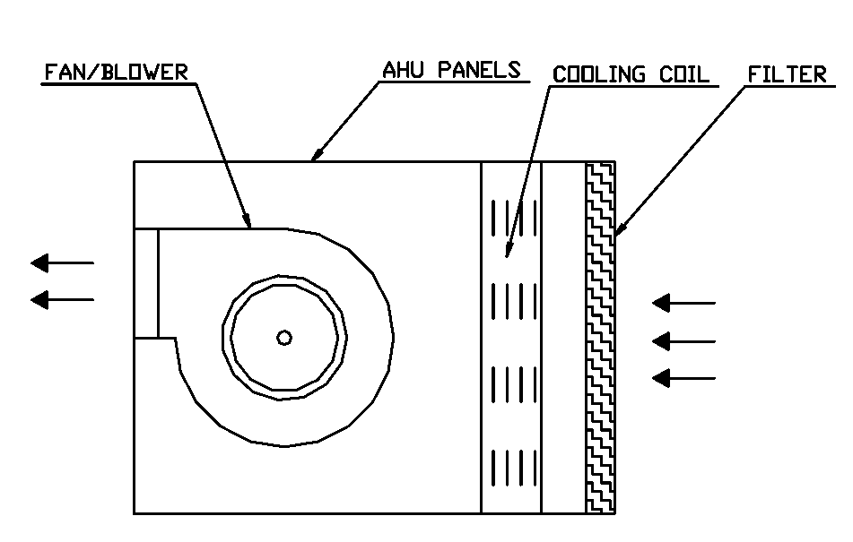
A typical AHU consists of the below components in place

Filters
European Standards EN 779& EN 1822
These standards are describing the classification & characteristic requirement of filters used in building ventilation & industrial process.
Based on the particulate size it classifies the filters as below
- Classes G1, G2, G3 & G4 – Defining the requirement of coarse dust particulate size > 10µ
- Classes M5, M6, F7, F8 & F9 - Defining the requirement of fine dust particulate size 1µ - 10µ
- Classes E10, E11, E12, H13, H14, U15 & U16 – Defining the requirement of suspended particulate sizes <1µ
Based on the type of filteration the filters are grouped together as below
- Coarse filter requirements are defined under classes G1-G4 of E 779
- Medium filter requirements are defined under classes M5-M6 of E 779
- Fine filter requirements are defined under classes F7-F9 of EN 779
- High-efficiency filter requirements are defined under classes E10-U16 of EN 1822
ISO 29463
It is derived from EN1822 and both are based on MPPS – Most Penetrating Particulate Size. MPPS is the particulate size at which an air filter gives minimum arrestance. But they have some differences in leakage test methods. Both standards are describing the requirement for high efficiency EPA, HEPA & ULPA filters.
ISO 16890
It replaces EN 779 from the year 2018. The EN 779 classifies the filters based on the filtration efficiency of particulate matter size of 0.4µ. Whereas ISO 16890 classifies the filters based on a spectrum of particulate sizes from 0.3µ to 10µ. It has three major classifications used by WHO (World health organization) as below
PM1 – Particulate sizes less than 1µ
PM2.5 – Particulate sizes less than 2.5µ
PM10 – Particulate sizes less than 10µ
The particulate matter >10µ are not breathed, the particulate matter <10µ can penetrate bronchi, the particulate matter <2.5 µ can penetrate pulmonary alveoli and the particulate matter <1 µ can penetrate alveoli capillary barriers.
European standard EN 15805
It describes the header framing dimensions of filter used in air intake systems and air handling units.
MERV–Minimum Efficiency reporting value
It is described in ASHRAE 52.2 to report the effectiveness of filters. It classifies the filters from MERV1 to MERV16. Higher the rating filters will allow fewer dust particles. This standard is intended to assist the end-user and specifier in their selection of appropriate filters for various applications.
Coil
All standard values in this document are referring to water as tube side fluid. Please refer AHRI 410 & ASHRAE standard for other fluids.
Chilled water details:
As per AHRI 410: 2001 the acceptable range of values are
- Chilled water inlet temperature 35° F ~ 65ׄ° F
- Water velocity - 1 fps ~ 8 fps
- Minimum fin surface temperature >32° F
- Minimum tube surface temperature >32° F
Typical values are
- Chilled water in & out temperature 45° F & 55° F
- Estimated Δt - 10° F
- Chilled water pressure drops - max. 20 ft H2O
- Flow rate - 2.4 gpm/ton
- Water velocity – 2fps~3fps
An increase in flow rate causes the velocity & pressure drop to increase. Then the water stays very little time inside the coil, which causes the air leaving temperature to grow and gives a reduced air Δt. To achieve the required air temperature and coil performance we may have to increase the number of fins/ft, which results in a price increase for the coil.
The maximum pressure drop across the coil falls between 20 ~ 24 ft H2O. But it is advisable to keep as low as possible and typical values fall less than 10 ft H2O. The pressure drop in the coil is controlled by the number of tubes in the coil.
The size, length & width of a coil is decided based on the fin length, design air face velocity, and required tonnage of the coil.
Fins
Aluminum is the standard material for fins used in most applications. Copper fins are recommended for corrosive environments. The number of fins various between 8 fins/inch to 14 fins/inch based on the heat transfer requirement.
When there is an increase in water flow rate the heat transfer rate reduces across the coil due to higher velocity, which requires fewer fins/inch. The required number of fins/inch will be close to 8. There will be a decrease in price for the coil, but we will end up with higher velocity & pressure drop.
Typical aluminium fin thickness falls between 0.006” ~ 0.0095”.
Tubes
With ½” tube OD, the performance will be increased slightly, and not a major difference between 5/8” tube OD. Like tube OD with an increase in tube thickness, there will not be a big difference in performance, only the coil life can be improved. The typical thickness for coils is 0.025” ~ 0.035”.
Number of rows in coil
A typical number of rows of a coil for AHU is 4. An increase in the number of rows results in more Δt, low discharge air temperature, more moisture removal& higher dehumidification & more air pressure drops for the fan.
Typically, an increased number of rows will be used where the intake to an AHU is 100% fresh air, like operation theatres.
Drain pan
A drain pan for individual coil section is expected, because the condensation in the upper coil may block the airflow in the lower one. And the main drain pan is required at the bottom of the full coil, which drains out the water.
Reynold’s number of an AHU coil is dependent on the tube inner diameter, fluid velocity & tube type. Reynold’s number can be controlled based on the circuit & adding a turbulator. Adding a turbulator may result in a higher pressure drop.
Refer latest AHRI 410 for the method of calculating Reynolds number and acceptable values.
Fouling
Fouling is the formation of sediments and any other matters that form inside the tube over a period. Fouling increases pressure drop reduces heat transfer, and obstruct fluid flow.
There is no straight method to calculate the fouling and it is the value directly added to thermal resistance for design & manufacturing of coil. This defines the duration for cleaning frequency.
The unit of fouling is ft²-°F-ht/Btu. Value zero will be considered for fouling when possible and the typical value will be 0.0005 for internal & 0.001 for external.
Air side details
As per AHRI 410: 2001 the acceptable range of values are
- Air face velocity – 200 fpm ~ 800 fpm
- Entering air dry-bulb temperature – 65° F ~ 100° F
- Entering air wet-bulb temperature – 60° F ~ 85° F
Typical values are
- Air face velocity – 500 fpm
- Entering air dry-bulb temperature –65° F ~ 80° F
- Entering air wet-bulb temperature – 60° F ~ 70° F
- Estimated Δt - 20° F ~ 25° F
When the air face velocity is too low heat transfer will not take place due to lack of turbulance. At the same time when the air face velocity is too high, the heat transfer will be very less with a higher air pressure drop. Also, moisture carry-over will happen at high velocity which results in water droplets all over the AHU. The air pressure drop will be very minimal at 400 fpm of face velocity, but there will be a slight increase in the cost of the AHU.
With the increased number of coil rows and fins, we get a higher air pressure drop.
As a rule of thumb 400 cfm is considered for 1TR capacity in a typical AHU. Refer to performance calculation for more details.
ASHRAE standard 33 – defines the equations for calculating air side pressure drop, sensible cooling, dehumidification, and test requirements.
AHU Panels
Outer skin & inner skin are usually made of galvanized steel. Aluminum and stainless steel materials are considered as alternate for specific requirements.
The insulation is selected based on the required thermal resistance & sound attenuation.
Single skin AHU
- Mainly for ventilation
- Outer casing shall be of – 0.5mm thick; with powder coated.
- Insulation of 25mm thick fibre glass or 15mm foam
- Suitable for lesser flow up to 2200 cfm
Double skin AHU
- Mainly for air conditioning
- Inner Skin – 0.4~0.7mm thick; galvanized steel
- Outer Skin – 0.4~0.9mm thick; with powder coated
- Insulation of 50mm thick fibre glass or 25mm foam; insulation is sandwiched between inner skin and outer skin.
Fans
| Forward curved fans | Backward curved fans |
|---|---|
| Forward curved fans will have many small blades curved in the direction of rotation. | Backward curved fans will have less quantity of longer blades curved opposite to the direction of rotation. |
| Flow is tangent to the rotation | Flow is in radial direction |
| Requires a scroll house to convert the kinetic energy into static energy | No housing is required |
| Smaller in size for a given air flow | Larger in size for a given air flow |
| Single inlet is suitable for high pressure low volume Double inlet is suitable for high volume, low pressure system | Suitable for higher efficiency & high pressure |
| Can run with AC motor | Requires an EC motor |
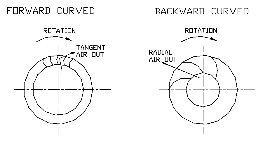
Typically, forward curved fans are used in AHUs due to the operational requirement, cost & size.
Operating above or below the optimum design criteria can cause noise and reduce the efficiency of the system for both forward & backward curved fans.
Internal static pressure (ISP) = Total pressure drop caused by all components within the system, like., filters, coils, mixing box and other components.
External static pressure (ESP) = It is the pressure developed in supply/return system / ducting, like., duct pressure loss, volume control dampers, diffusers, and other components.
Total static pressure (TSP) = ESP + ISP
Each component (filters, dampers, diffusers, grills, ducts, etc) in the given system produces some static pressure to the fan. The static pressure to the fan is directly proportional to the flow and at the same time, the fan cannot be operated above or below the optimum levels.
Additional information
Additional details to be considered in selecting an AHU are given below and we are not covering in this article.
- Drip eliminator,
- Anti-corrosive coating to the coil
- Variable frequency drives for fans
- Humidifiers
- De-humidification
- Belt drive / Direct dive for the fans
- Selection of pulley and belts
- Volume control dampers