
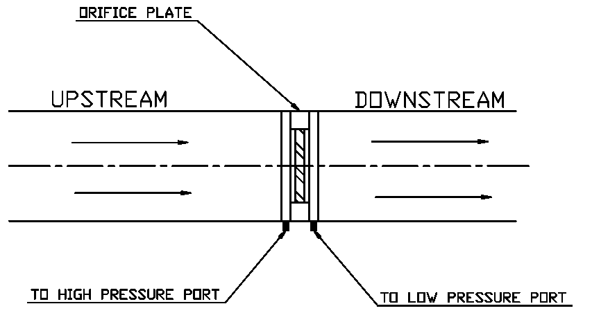
Using Orifice plate & Manometers
Best suitable for liquid flow measurements.
Manufacturers:
| Electronic Manometers | Orifice plate |
|---|---|
| Camdronic | Dwyer |
| Poddymeter | Honeywell |
| Testo |
We can easily measure the water flow rate when we have an orifice plate on the chilled water pipeline.
When we install an orifice plate on the system, the pressure drop across the orifice can be 50% of differential pressure. Therefore, it is advisable to install the orifice plate on a by-pass line with shut-off valves.
Installation of the Orifice plate requires some set of criteria and have mentioned a few below.
Refer manufacturer datasheet for more information.
Install the orifice plate on a horizontal line. Refer manufacturer data for minimum pipe lengths upstream and downstream.
For the liquid line, install the orifice plate so that the differential ports are at the bottom of the water pipe to avoid air.
For the gas line, install the orifice plate so that the differential ports are at the top of the gas pipe to avoid solid particles.
Please refer to ISO 5167 for the measurement of flow using an Orifice plate.
Using any one of the methods mentioned at the bottom of this article, measure the differential pressure between the high-pressure port & the low-pressure port.
Calculate the volume flow rate across the orifice using the below equation.
For Water
Refer manufacturer data for Co-efficient “K” usually falls between 0.6 ~ 0.9
The above equation can be written as
where, - Diameter of Orifice plate - Differential pressure - Density of Water
Using Balancing Vale & Manometers:
Best suitable for liquid flow measurements.
Manufacturers:
| Valves |
|---|
| Belimo, Crane |
| FlowCon, Danfoss |
| Honeywell, Johnson Controls |
| Preso, Schneider, and Siemens |
We can easily measure the water flow rate when we have a balancing valve with flow measuring test ports on the chilled water pipeline.
Installation of Orifice plate/Balancing valve requires below criteria as below, and refer manufacturer datasheet for more information.
Refer manufacturer datasheet for installation instruction & the Kvs value of balancing valves.
Using any one of the methods mentioned at the bottom of this article, measure the differential pressure between the high-pressure port & the low-pressure port. Calculate the volume flow rate using the below equation.
For Water
Calculate the volume flow rate across the balancing valve using the below equation.
Where, - Amount of flow at fully opened condition across a regulating valve (Refer manufacturer data) - Differential pressure
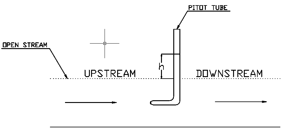
Using a simple Pitot tube
Best suitable for liquid flow measurement on an open stream(example: River).
A pitot tube is a tube that is large enough for the capillary effect to be negligible.
For Water
Calculate the flow velocity using the below equation.
Where, - Gravitational force - Head on pitot tube
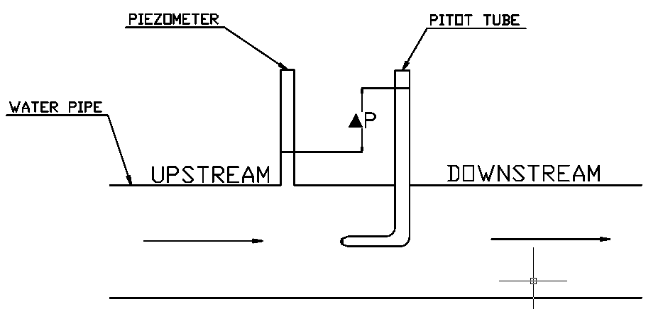
Using Pitot tube with Piezometer
Best suitable for liquid flow.
The pressure sensed by the pitot tube is only the stagnation pressure.
For a closed pipeline, it is mandatory to measure the static pressure.
Measure the static pressure on the walls of the pipe with the help of a Piezometer.
Piezometer is widely used in the groundwater system. We can not use Piezometer for gas or vacuum. The pressure should be reasonably low; otherwise, we need a long vertical pipe.
For Water
Calculate the flow velocity using the below equation.
Where, - Differential pressure - Density of Water
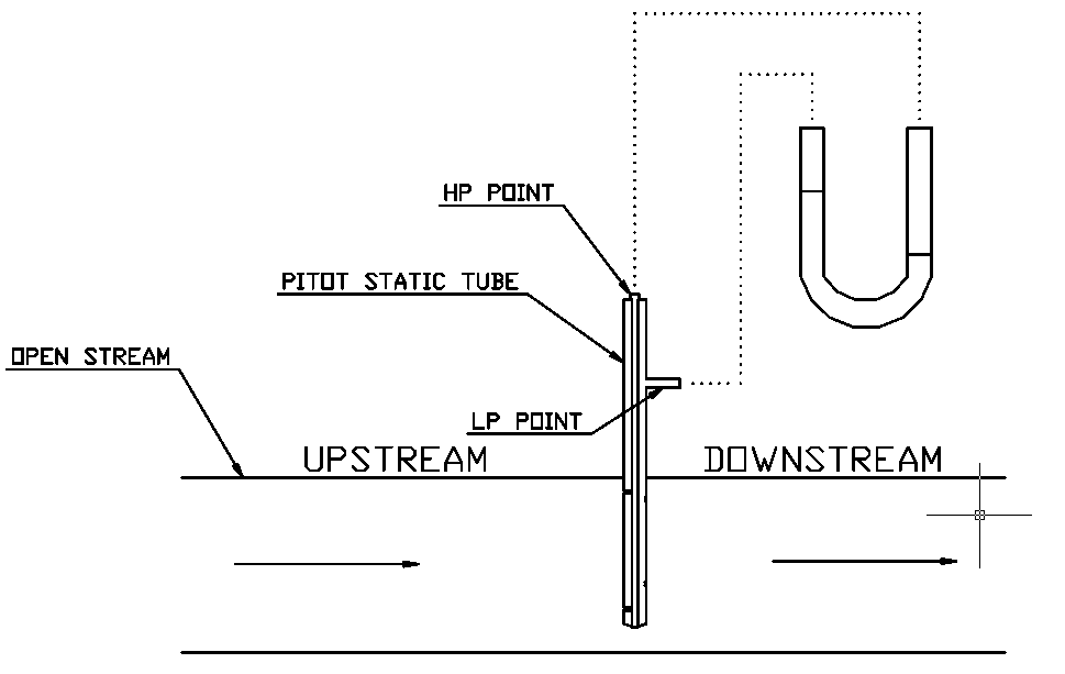
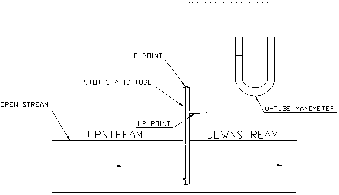
Using Pitot static tubes & DP Manometer
Best suitable for liquid & gas flow measurement.
Manufacturers:
| Pitot tubes |
|---|
| Extech |
| Dwyer |
We can measure the statice pressure and stagnation using a single instrument called Pitot Static Tube.
The single tube with a dual wall having holes on one shell for upstream and holes on another shell for downstream. The upstream holes will sense high pressure(Stagnation pressure), and the downstream holes will sense low pressure (static pressure).
Install the pitot static tube in which the high-pressure port is pointing to the upstream. And the pitot tube should be perpendicular to the flow direction.
We shall install the pitot static tube on a straight horizontal pipeline which should have below minimum lengths on the upstream and downstream. The rule of thumb is
10-15 times pipe diameter for upstream 5 times pipe diameter for downstream
Refer manufacturer datasheet for exact values.
Using any one of the methods mentioned at the bottom of this article, measure the differential pressure between the high-pressure port & the low-pressure port.
For Water
Calculate the flow velocity using the below equation.
Where, - Differential pressure - Density of Water - is a correction factor considered for friction, static to dynamic conversion loss, geometrical loss. The manufacture calculates this value from calibration tests. Refer manufacturer datasheet for this value.
Differential Pressures:
We can use the below types of equipment to calculate the differential pressure,
– Differential pressure gauges – U-tube manometers – Electronic differential pressure manometers
| Differential pressure gauges | Electronic differential pressure manometers | U-tube manometers |
|---|---|---|
| Testo | Fieldpiece | Honeywell |
| Magnehelic/Capsuhelic | Camdronic | RS components |
| Extech | FlowTech | |
| Testo |